Dredging Planning & Services
Depending upon where you are dredging working through your plan can take over a year. Mistakes will cost time, money and erode stakeholder trust.
Consulting Services |
GET STARTED
Contact us about dredge engineering, equipment, pumping, and dewatering to
meet your contract
requirements.
Dredge Project Planning
From project planning to evaluation and completion – we will guide you every step of the way.
- Feasibility Research and Scoping
- Determining the most adequate dewatering and dredging alternatives for your project
- Taking care of evaluations and approvals including environmental, geotechnical, planning, and legal.
- Careful management that ensures the most optimal process, including Acid Sulfate Soil (ASS) management
- Thorough monitoring including benthic macroinvertebrate
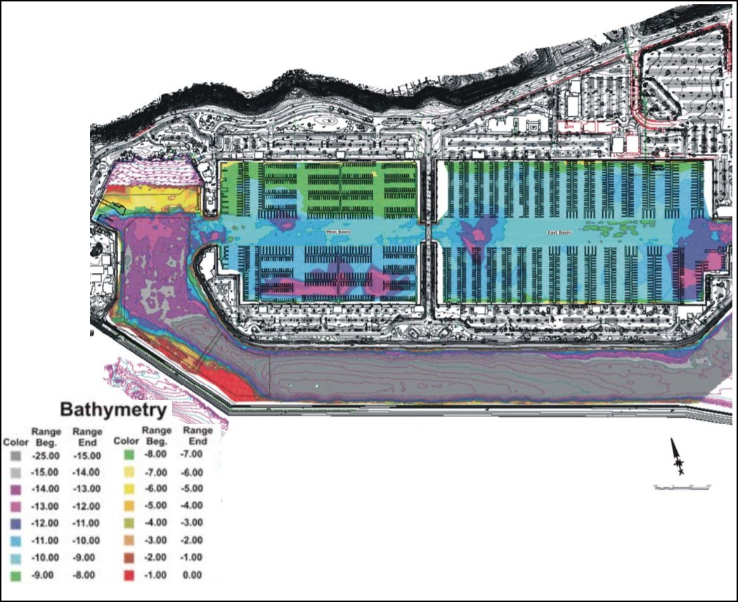
We have in-house equipment and the ability to include hydrographic surveys, as well as surveys before and after the dredge of certain areas. Other environmental-related services are also available.
We use special software like AutoCAD and Civil3D to get the plans and drawings properly ready and carefully designed according to the project characteristics.
Apart from these, we also use GIS, analysis, and data integration to finish the task.
The main GIS capabilities are:
- Mapping – presentation, environmental and multi-attribute thematic mapping
- Digital elevation models
- Analysis such as volumetric analysis and overlay analysis
The concept design that incorporates digital 3D model development is an important part of the project. Our visualization services help out in terms of presentation of the concept design, volume distribution, analysis (for example shadow analysis), grading plans, as well as environmental attributes.
Our specialists are highly experienced in handling complex data sets and their graphical presentation, as well as database management and analysis.
A significant part of our offer is represented by GIS & CAD services. We use these systems to plan, visualize, and analyze the dredging project so that all the projects can be successfully completed, even challenging, or large projects.
Our diversified offer allows us to guide you from start to finish, as well as to deliver the right equipment for your dredging project in various stages of completion.

Dredged Material Management
The alternatives available for managing dredged materials include:
• open water placement that involves the discharge of dredged material directly to the lake or river;
• beach/littoral nourishment, which is the placement of dredged material directly onto a beach or into shallow water;
• capping, which is the placement of a contaminated dredged material on the level bottom or in a subaqueous pit and covering the material with a layer of clean material;
• beneficial use at upland sites, including construction fill, landscaping, landfill cover, agricultural soil amendment, etc;
• confined disposal at a CDF or disposal at a licensed landfill, and;
• treatment of sediments to enable unrestricted disposal or beneficial use of some or all of the treated soils.
The selection of the most appropriate alternative for managing dredged material should consider the materials physical properties, levels of contamination, the quantity of material to be dredged, availability and suitability of disposal sites, as well as economic, social, and other factors.
If a dredged material is not suitable for open water disposal, beneficial use, or capping, the only remaining alternatives are confined disposal and treatment.
Federal regulations that have been applied to the management of dredged material from Great Lakes harbors and channels include:
• Clean Water Act, Section 401 (Water Quality Certificate);
• Clean Water Act Amendment of 1972, Section 404 (Section 404 Permit);
• Rivers & Harbors Act of 1899, Section 10;
• Coastal Zone Management Act of 1972;
• National Environmental Policy Act (NEPA) of 1969;
• Fish & Wildlife Coordination Act of 1934, and;
• Endangered Species Act of 1973
Dredged Material Containment
Confined disposal has been, and remains the most commonly used management alternative for contaminated sediments.
CDFs have been designed to perform three basic functions:
• physical containment of dredged material;
• management of water within the site, and;
• environmental protection.
All confined disposal facilities are designed to permanently contain a volume of dredged material determined from estimates of future dredging needs. Dikes, or berms are constructed to contain the dredged material laterally. The nature of these dikes is quite different for in-water and upland CDFs.
Most in-water facilities provide containment using rubble mound dikes constructed with stone gravel and occasionally using sheet piling. In most cases, these dikes look very much like a breakwater, having outer layers of large stones, weighing up to a ton or more, to protect the Great Lakes Confined Disposal Facilities: April 2003 13facility from wave energy. The center, or core of the dike is typically composed of smaller stone, gravel or sand. Four basic types of dike designs are utilized at most of the Great Lakes in-water CDFs:
• circular sheet pile cells: interlocking circular steel sheet pile cells with random, granular fill and armor stone at dike toe
• soldier-pile stone dike: a trapezoidal stone dike with steel sheet pile in the center of the dike to provide vertical stability and allow steeper side slopes, armor stone on both sides of dike, and a small core with variable stone or gravel sizes
• layered core dike: a trapezoidal stone dike with armor stone on outside of dike, not always on inside and a core consisting of two or more layers of stone, gravel, sand
• mono-layer core dike: a trapezoidal stone dike with armor stone on outside of dike, not always on inside, and a core consisting of single grade of stone, commonly 4-inch minus limestone
Stone sizes on in-lake CDFs were typically designed to withstand a 20-year storm. Dike height was typically designed to limit overtopping by waves with a 20-year lake level and a 20-year storm. The gradation of the material in the core of the dike was based on availability and construct-ability concerns in most cases. The sizing of granular material in CDFs with layered cores included some consideration of their ability to retain sediment particles inside the CDF
In most cases, upland CDFs were constructed with earthen dikes, which are like berms used for landscaping, levees or landfills. The side slopes of earthen dikes are generally more shallow (flatter) .
GET STARTED
Contact us about dredging consulting, equipment, pumping and dewatering to meet your contract requirements.


