Creating a Closed Loop System for Fly Ash Dredging and Dewatering
From Recycle Pond to Landfill Placement
The Fly Ash Dredging and Dewatering Process Involves:
1. Hydraulic dredging of residuals from the Recycle Basin Pond
2 . Long-distance pumping of residuals with a distance of approximately 1,300 meters and a 28 meters increase in elevation, mechanical dewatering of the residuals at the on-site Combustion Waste Storage Area landfill site
3. Direct placement of the dewatered residuals on the landfill face, and treatment of the process filtrate to remove solids so that stringent 200 ppm TSS levels could be maintained for returning all process water to the Recycle Pond.

The process uses mechanical separation and dewatering of coarse sediments with screens and the addition of polymers to enable mechanical dewatering of the fine sediments.
This method would include hydraulic dredging of the sediments from the slurry pond; pumping of the sediments to the landfill site; mechanical dewatering of the sediments at the landfill; direct placement of dewatered sediments into the landfill; and a water treatment and clarification process for treatment of process effluent to meet the 200 ppm TSS standard.
Project Implementation
1. Depending if you have a liner or not, select a dredge cutter or auger head equipped with wheels to prevent the head from disturbing the sand layer or liner.
2. Silt curtains can be used to keep solids from reaching the intake as dredging continues the silt curtain can be moved as dredging progressed from the east end towards the west
3. Progress surveys in conjunction with flow monitoring, solids sampling of the dredge slurry, dewatered sediments and return flow are used to determine dredge quantity volume.
The following key pieces of equipment are required for sediment removal and dewatering operations:
- Auger/cutter dredge
- 8″ centimeters booster pump
- 8″ Centimeters DAE Dredge Pipe
- Hydrocyclones and Dewatering Screen System
- 4 – Trailer Mounted 2.2 Meter Charter Belt Filter Presses
- 170,000 liters Inclined Plate Clarifier System
- 30 meters by 30 meters Polishing Tank
Create a Pipe Route from your Dredging Site to Your Dewatering Site Landfill Area:

Landfill Sediment Dewatering Operations
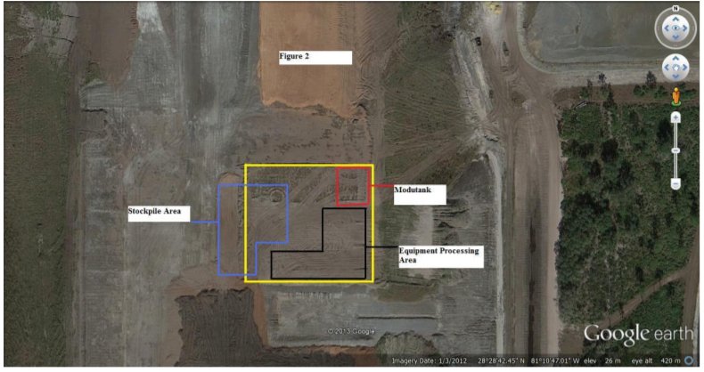
A level compacted pad for placement of the equipment needs to prepared at your dewatering location.

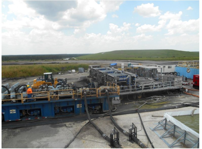
The dredge will pump the solids in a slurry through the pipeline to a booster pump, which will pump the slurry to your dewatering equipment staging pad. The dewatering unit can separate the material into three phases for disposal using a series of pumps, screens and hydrocyclones. The coarse grained is captured using hydrocyclones and dewatered on screens and discharged for loading into a stockpile.
An 80,000 liters mix/storage tank was placed in-line between the multi-stage mechanical dewatering unit and belt presses can provide a homogeneous feed to the dewatering equipment. You can use a mix tank to receive the fine grained sediments which were not removed by screens and hydrocyclones. These fine grained sediments can be conditioned with a polymer to enhance the dewatering process. Trailer mounted 2.2 meter belt filter presses can be utilized to dewater these solids and discharged into a stockpile. Power for the processing equipment can be furnished by a 500KW diesel powered generator.
A photo of the dewatering process is shown below.

The filtrate from this stage of dewatering was discharged into a trailer mounted clarifier unit. Solids collected in the clarifier were returned to the belt filter press operation for dewatering. The filtrate from the clarifier was discharged into a lined 30 meter by 30 meter Modutank which was stationed adjacent to the dewatering equipment staging pad. The filtrate from the Modutank was discharged through a fuse welded pipe into the influent structure at the Landfill Leachate Pond for return to the RB. If TSS samples exceed 200 ppm, dewatering operations would be shut down until this limit could be achieved.
A photo of the filtrate treatment process is below.

The unit cost for hydraulic dredging, mechanical dewatering and landfill placement was approximately $32 per cubic meter of sediment removed from the RB.
The dredge operated for approximately 38% of the operating day, as the dewatering equipment capacity could not handle the full flow of the dredge slurry. The average dredge pumping rate was approximately 6,800 lpm while the average process rate of the dewatering equipment was approximately 2,650 lpm.

This project demonstrated that a closed loop dredging and dewatering process could be used to remove sediments from an active, in-service basin at a power plant with minimal impact to plant operations. All coal sediments residuals that were removed from the basin were disposed on-site at the landfill. All water used during the process was recycled into the plant water management system and returned to the Recycle Basin for reuse in the operation of the plant.


